
Product advantages of Sandvik CS/CH Cone Crusher
1、Sandvik CS/CH Cone Crusher by selecting different crushing cavity types and adjustable eccentric distance.
2、Sandvik CS/CH Cone Crusher can easily adapt to different production requirements. Because of its inherent flexibility, users can meet most of the production needs in the future with constant changes. Whether it is two-stage crushing or three-stage crushing, it is a reasonable choice.
3、Sandvik CS/CH Cone Crusher provides automatic overload protection and is equipped with intelligent ore discharge adjustment system, which greatly improves the utilization rate of equipment and automatically adapts to the change of feeding conditions.
4、 Through regular inspection and its own compensation system, users can make full use of the crusher liner, and even if the liner is worn, it can also ensure the production capacity and specification requirements of the product.
5、The automatic safety protection of the hydraulic control system is provided with the adjustment function of the ore discharge port.
6、A heavy hydraulic cylinder is used to support the main shaft and adjust its position. With automatic overload protection, the iron block or other non-breakable materials can pass safely in production, and the spindle can return to its original position automatically.
7、Monitor the actual crushing load and relevant parameters inside the crusher in the whole process to ensure the maximum production capacity.
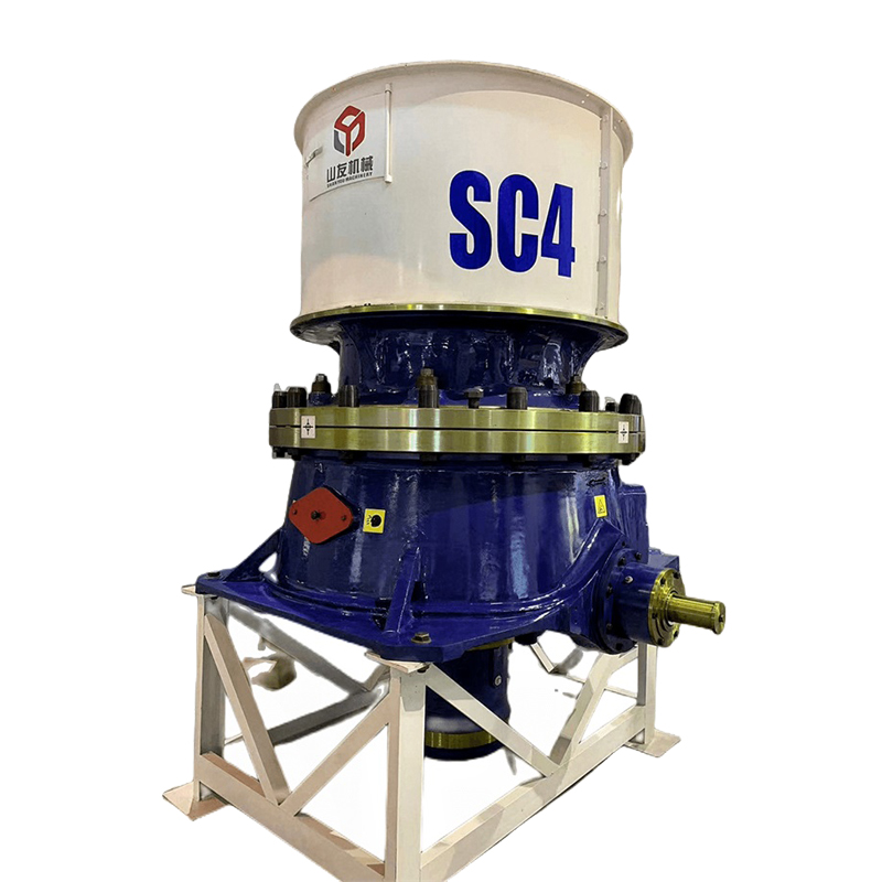
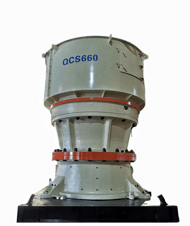
8、 Sandvik CS/CH Cone Crusherinclude the CS and CH series. In our company, the CS440 cone crushers and CS660 cone crushers are the best-selling, while the CH series is the CH660 cone crushers that are popular.
9、In addition to the CS440 cone crusher, CS660cone crusher, and CH660cone crusher, other models are also popular.
Technical parameter of Sandvik CS/CH Cone Crusher
| Model | Max feeding size (mm) | Rang of ore out fall (mm) | Weight (kg) | Motor power (kw) | Capacity (t/h) |
| CH420 | 135 | 4-35 | 5300 | 90 | 22-128 |
| CH430 | 185 | 5-38 | 9200 | 132 | 37-219 |
| CH440 | 215 | 6-44 | 14300 | 250 | 68-413 |
| CH660 | 275 | 10-51 | 23500 | 315 | 143-662 |
| CH870 | 300 | 10-70 | 50000 | 520 | 280-1512 |
| CH880 | 370 | 8-70 | 66500 | 600 | 309-2128 |
| CS420 | 240 | 19-38 | 6800 | 90 | 70-168 |
| CS430 | 360 | 19-51 | 12000 | 160 | 91-344 |
| CS440 | 450 | 25-54 | 19300 | 250 | 195-601 |
| CS660 | 560 | 38-83 | 36500 | 315 | 318-1050 |


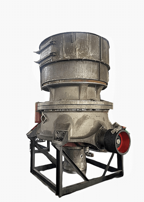
Parts of Sandvik CS/CH Cone Crusher

Factory Introduction 🔗
Our factory has a history of more than 20 years, covering a total area of 36000 square meters, and equipped with advanced production equipment. In our factory, we have produced more than 1000 sets of mining equipment. With our reliable quality assurance and high-quality after-sales service, we have won the unanimous praise of the majority of users.
Our company's products mainly include mining equipment such as cone crushers, rotary crushers, jaw crushers, ball mills, etc. The equipment specifications range from large to small, with complete models. At present, there are many categories of cone crushers in our company's main core products. In addition to the classic spring crushers, our company's subsequent main HP/MC multi cylinder cone crushers and CH-CS/SC single cylinder crushers are all manufactured according to the imported original drawing 1:1, which can replace the original imported crushers. Due to their high cost-effectiveness and timely after-sales service, they have received recognition and support from many customers. (For specific details, please refer to the product information on the official website)
Our company also has long-term stock of accessories and vulnerable parts, such as Symons, Sandvik, and Mesto, which can be interchanged with original accessories. Simply provide the original part number to produce, and the materials and dimensions meet the original quality. This allows users to use and purchase with confidence before and after purchase, ensuring production.


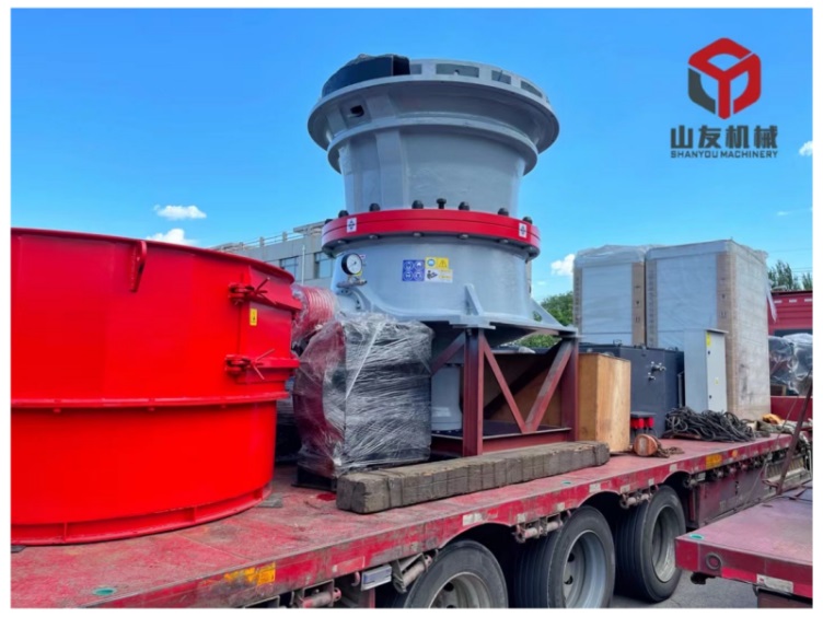
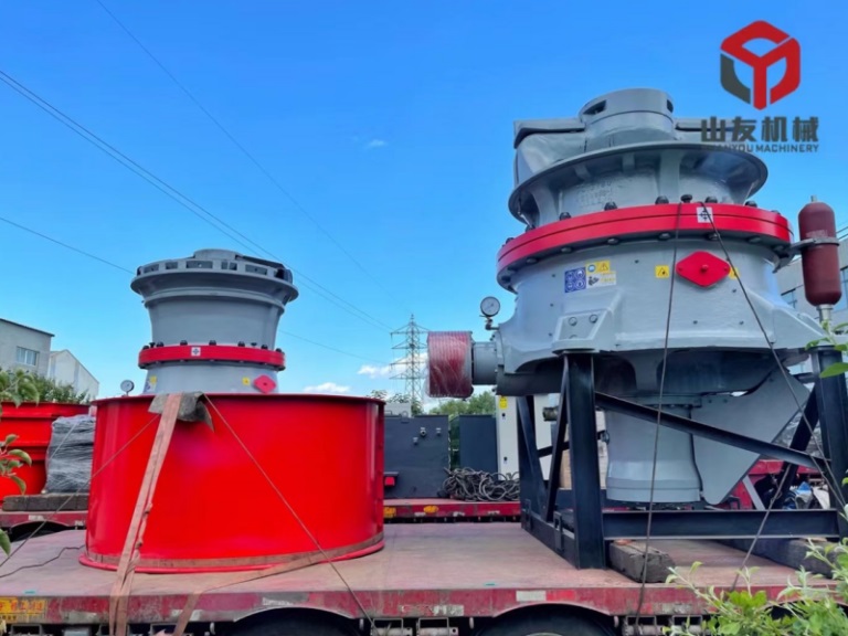
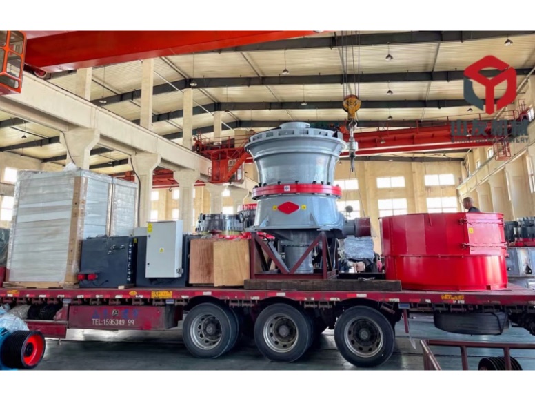
Packing of Sandvik CS/CH Cone Crusher 🔗


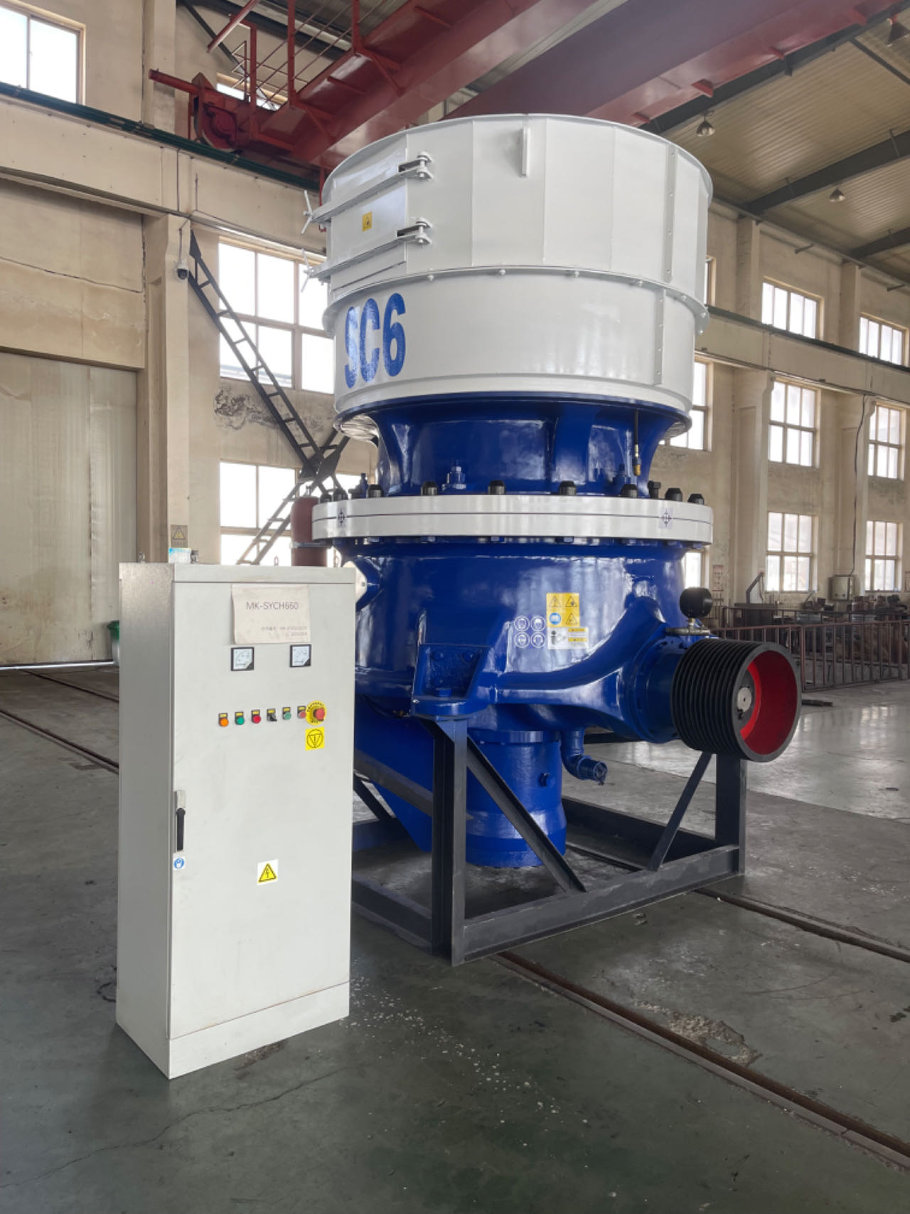
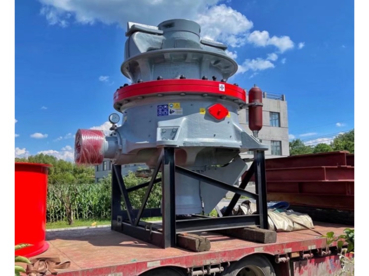
On site photos of Sandvik CS/CH Cone Crusher 🔗


Installation instructions of Sandvik CS/CH Cone Crusher
01. Installation of Underframe
1) The equipment is placed on the basis of construction.
2) Equipment placement: The equipment needs to be pre embedded with anchor bolts according to the foundation drawing (according to user requirements, anchor bolts can also be omitted and a pre embedded iron scheme can be used):
a. Perform the second grouting according to the position of the foundation bolts on the foundation drawing.
b. After the secondary grouting layer hardens, install the base frame.
3) When installing the underframe, strict levelness should be maintained. Before installation, the corresponding positions of the underframe damping pads must be polished flat, and the foundation levelness should be checked with a level gauge.
4) Maintaining the levelness of the base can ensure the dynamic balance of the equipment, thus effectively ensuring the reliability of the machine.
02. Installation of transmission components
1) The bearings are hot installed, and the axial position of the bearings relative to the transmission shaft should be ensured when installing the transmission shaft.
2) After installing the transmission shaft, the axial movement should be checked.
3) When installing the gland and host pulley, a layer of sealant must be applied to the flat contact part and flat key surface.
4) The disassembly of the host pulley can be done using a hydraulic device.
03. Installation of exciter components
1) The exciter component has three eccentric blocks, with keys corresponding to the upper and lower eccentric blocks and the shaft sleeve. There are three sets of keyways on the shaft sleeve, which can be replaced with different sets of keyways to extend the service life of the shaft sleeve.
2) There are multiple keyways on the outer side of the fan-shaped part of the three eccentric blocks. The long key fixes the middle eccentric block through the force of the upper and lower eccentric blocks. When in use, the relative positions of the middle eccentric block and the upper and lower eccentric blocks can be changed as needed to obtain different crushing forces.
3) When loading and unloading eccentric blocks, a small angle wedge can be used to expand the opening of the eccentric block slightly for easy loading and unloading.
4) Lock the eccentric block using high-strength steel bolts to sink the nut into the open groove on one side. If due to conditions, other high-strength bolts can only be used on site, it must be ensured that the bolts do not rotate by 90 ° after sinking. Otherwise, thin iron plates should be welded on either symmetrical side of the nut to ensure that the nut can be locked by the open groove.
5) After tightening the nut so that the two planes at the opening are parallel, use a one meter long force rod to tighten the nut again to a certain angle when applying pre tightening force. After applying pre tightening force, lock the nut.
6) Install two locking plates, which are close to the eccentric block. If there is a gap between the upper surface and the axial keyway of the shaft sleeve, a thin iron plate can be placed under the locking plate to compensate for the gap. Tighten the bolts and lock them tightly.
04. Installation of exciter components and dynamic cone support
1) To ensure uniform and fine contact, the auxiliary support spherical pad should be scraped and polished in conjunction with the dynamic cone support steel pad, and every 25mm on the outer ring of the spherical pad should be ensured × 25mm has 10-15 contact points, while also providing a small annular gap in the inner ring.
2) Place the vibration exciter flat on the ground, with the movable cone support located on it. Place the flange on the shaft sleeve, install the cone sleeve and snap ring, and ensure that the snap ring fits into the circumferential keyway of the shaft sleeve and sinks into the step of the cone sleeve.
3) Slowly lift the movable cone support to allow the exciter to detach slightly from the ground. Tighten the 8 bolts on the flange step by step, repeatedly, and symmetrically, and then lock the bolts in pairs with iron wire.
4) The correct installation of the auxiliary support spherical pad and exciter is conducive to ensuring the reliability of equipment operation.
05. Installation of moving cone components
1) Remove the protective oil layer from the coated spindle, spherical surface, and conical surface.
2) Apply a layer of yellow dry oil to the surface of the spindle, and a layer of thin oil to the spherical and conical surfaces.
3) Wrap the spindle with thin plastic paper to prevent contamination.
4) Place the moving cone on an iron frame, weld two symmetrical lifting rings on the outer surface of the moving cone lining plate, lift the moving cone lining plate and install it on the moving cone. Install the small lining plate, backing ring, and cap nut (left-hand thread), and then use a special wrench and sledgehammer to tighten the cap nut. Use a feeler gauge to check the gap between the surrounding moving cone lining plate and the moving cone, ensuring that the gap is almost zero and consistent all around.
5) During assembly, lift the moving cone component at the cap nut, gently and slowly place the main shaft of the moving cone into the shaft sleeve of the vibration exciter component, and steadily make the spherical surface of the moving cone contact the spherical pad of the moving cone support, avoiding the tongue shaped ring or outer edge of the moving cone from being elevated on the moving cone support and damaging the sealing ring.
06. Installation of adjustment ring
1) The adjustment ring components include the hopper, threaded ring, and fixed cone lining plate, and their installation quality can also affect the stability of equipment operation, crushing effect, and the service life of the fixed cone lining plate.
2) The fixed cone lining plate and the threaded ring come into contact through the conical surface. During installation, place the fixed cone lining plate in a correct position, place the threaded ring directly on it, place the flange on the threaded ring, clamp the snap ring onto the outer ring of the neck of the fixed cone lining plate, and then tighten the bolts one by one, repeatedly, and symmetrically to lift and clamp the flange.
3) After installing the fixed cone lining plate, components such as the pressure iron, sealing ring, and hopper can be installed.
07. Installation of locking mechanism
1) Determine the relative position of the locking structure and support ring based on the positioning pin, screw in the adjustment ring, and adjust to the appropriate position to obtain a suitable working discharge gap.
2) Always ensure that the locking structure is parallel to the support ring, open the high-pressure pump station, adjust the pressure to 13MPa, and gradually, repeatedly, and symmetrically screw down the top rod of the locking structure jack until it is completely tightened.
3) Turn off the high-pressure pump and remove the remaining pressure from the high-pressure pump.
4) Due to the locking structure being achieved through disc springs, the high-pressure pump cannot be opened during normal equipment operation.
08. Installation of lubrication device
1) The lubrication device is installed according to the assembly diagram provided by our company, and users need to prepare the required HG4-761-74 oil pipes and other parts for installation. The oil inlet hose must be able to withstand a pressure of>10MPa.
2) The configuration of the lubrication device must ensure smooth lubrication of oil inlet and return.
3) After completing the installation of the lubrication device, the lubrication device should be tested first, and the lubrication system and control should be debugged. If any faults are found in the lubrication system, they must be disassembled and repaired.
4) It is also necessary to debug the temperature and pressure control system of the lubrication device, and check the reliability of the electrical contact pressure gauge and temperature gauge, as well as their connection with the electrical control cabinet, by adjusting the pressure and temperature upper and lower limit pointers, to ensure the reliability of the equipment control system.