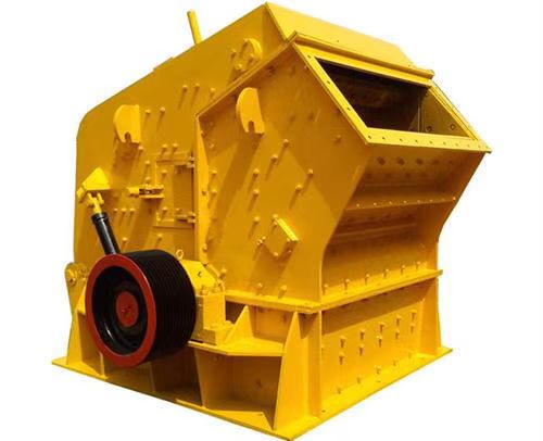

Product advantages of NP Type Impact Crusher
1、Compact Impact Crusher With Large Crushing Ratio is the best solution to meet the increasingly demanding requirements of increasing production and efficiency. In addition to the fixed crusher described on this page, there are also many mobile or portable impact crushing stations.
2、By adding different options, such as the fully hydraulic impact plate discharge port adjustment device, the third stage impact plate, or different grades of manganese steel and high chromium plate hammer with ceramic inserts, you can configure the impact crusher to meet your needs.
3、In addition, Compact Impact Crusher With Large Crushing Ratio automatic control system can control the crusher and display complete performance parameters, which can also realize remote operation and adjustment for 11 years.
4、Easy maintenance
Compact Impact Crusher With Large Crushing Ratio designed with high mechanical strength. When maintenance is required, parts replacement is simple and convenient.
5、Compact Impact Crusher With Large Crushing Ratio all models can be equipped with rotor rotation system. When replacing the plate hammer or adjusting the discharge port, the rotor can be positioned without entering the crusher.
Technical parameter of NP Type Impact Crusher
| Model | Crushing range | Weight(kg) | Rated installed power | Max installed power | Feeding port | Max feed size(mm) |
| NP1313 | Coarse crushing | 17 800 kg (39 249 lbs) | 200 kW / 250 hp | 250 kW / 350 hp | 1 320 x 1 225 mm (52" x 48 1/4") | 900 mm (35") |
| NP1415 | Coarse crushing | 22 330 kg (49 230 lbs) | 250 kW / 350 hp | 315 kW / 400 hp | 1 540 x 1 320 mm (60 5/8 " x 52") | 1 000 mm (40") |
| NP1620 | Coarse crushing | 41 240 kg (90 920 lbs) | 400 kW (2x200 kW) / 500 hp (2x250 hp) | 500 kW (2x250 kW) / 700 hp (2x350 hp) | 2 040 x 1 634 mm (80 1/4 " x 64 1/4") | 1 300 mm (51") |
| NP2023 | Coarse crushing | 80 600 kg (177 700 lbs) | 1 000 kW (2x500 kW) / 1300 hp (2x650 hp) | 1200 kW (2x600 kW) / 1600 hp (2x800 hp) | 2 310 x 1 986 mm (91" x 78 1/4") | 1 500 mm (59 |
| NP1110 | Intermediate fragmentatio | 9 250 kg (20 396 lbs) | 160 kW / 200 hp | 200 kW / 250 hp | 1 020 x 820 mm (40 1/4 " x 32 1/4") | 600 mm (24") |
| NP13 | Medium and fine crushing | 11 700 kg (25 700 lbs) | 250 kW / 350 hp | 315 kW / 400 hp | 1 320 x 560 mm (52" x22") | 350 mm (14") |
| NP15 | Medium and fine crushing | 16 130 kg (35 567 lbs) | 315 kW / 400 hp | 355 kW / 450 hp | 1 540 x 600 mm (60 5/8 " x 24") | 400 mm (16") |
| NP20 | Medium and fine crushing | 26 750 kg (58 975 lbs) | 500 kW (2x250 kW) / 700 hp (2x350 hp) | 630 kW (2x315 kW) / 800 hp (2x400 hp) | 2 040 x 700 mm (80 5/16" x 27 9/16" ) | 400 mm (16") |
Installation instructions
01. Installation of Underframe
1) The equipment is placed on the basis of construction.
2) Equipment placement: The equipment needs to be pre embedded with anchor bolts according to the foundation drawing (according to user requirements, anchor bolts can also be omitted and a pre embedded iron scheme can be used):
a. Perform the second grouting according to the position of the foundation bolts on the foundation drawing.
b. After the secondary grouting layer hardens, install the base frame.
3) When installing the underframe, strict levelness should be maintained. Before installation, the corresponding positions of the underframe damping pads must be polished flat, and the foundation levelness should be checked with a level gauge.
4) Maintaining the levelness of the base can ensure the dynamic balance of the equipment, thus effectively ensuring the reliability of the machine.
02. Installation of transmission components
1) The bearings are hot installed, and the axial position of the bearings relative to the transmission shaft should be ensured when installing the transmission shaft.
2) After installing the transmission shaft, the axial movement should be checked.
3) When installing the gland and host pulley, a layer of sealant must be applied to the flat contact part and flat key surface.
4) The disassembly of the host pulley can be done using a hydraulic device.
03. Installation of exciter components
1) The exciter component has three eccentric blocks, with keys corresponding to the upper and lower eccentric blocks and the shaft sleeve. There are three sets of keyways on the shaft sleeve, which can be replaced with different sets of keyways to extend the service life of the shaft sleeve.
2) There are multiple keyways on the outer side of the fan-shaped part of the three eccentric blocks. The long key fixes the middle eccentric block through the force of the upper and lower eccentric blocks. When in use, the relative positions of the middle eccentric block and the upper and lower eccentric blocks can be changed as needed to obtain different crushing forces.
3) When loading and unloading eccentric blocks, a small angle wedge can be used to expand the opening of the eccentric block slightly for easy loading and unloading.
4) Lock the eccentric block using high-strength steel bolts to sink the nut into the open groove on one side. If due to conditions, other high-strength bolts can only be used on site, it must be ensured that the bolts do not rotate by 90 ° after sinking. Otherwise, thin iron plates should be welded on either symmetrical side of the nut to ensure that the nut can be locked by the open groove.
5) After tightening the nut so that the two planes at the opening are parallel, use a one meter long force rod to tighten the nut again to a certain angle when applying pre tightening force. After applying pre tightening force, lock the nut.
6) Install two locking plates, which are close to the eccentric block. If there is a gap between the upper surface and the axial keyway of the shaft sleeve, a thin iron plate can be placed under the locking plate to compensate for the gap. Tighten the bolts and lock them tightly.
04. Installation of exciter components and dynamic cone support
1) To ensure uniform and fine contact, the auxiliary support spherical pad should be scraped and polished in conjunction with the dynamic cone support steel pad, and every 25mm on the outer ring of the spherical pad should be ensured × 25mm has 10-15 contact points, while also providing a small annular gap in the inner ring.
2) Place the vibration exciter flat on the ground, with the movable cone support located on it. Place the flange on the shaft sleeve, install the cone sleeve and snap ring, and ensure that the snap ring fits into the circumferential keyway of the shaft sleeve and sinks into the step of the cone sleeve.
3) Slowly lift the movable cone support to allow the exciter to detach slightly from the ground. Tighten the 8 bolts on the flange step by step, repeatedly, and symmetrically, and then lock the bolts in pairs with iron wire.
4) The correct installation of the auxiliary support spherical pad and exciter is conducive to ensuring the reliability of equipment operation.
05. Installation of moving cone components
1) Remove the protective oil layer from the coated spindle, spherical surface, and conical surface.
2) Apply a layer of yellow dry oil to the surface of the spindle, and a layer of thin oil to the spherical and conical surfaces.
3) Wrap the spindle with thin plastic paper to prevent contamination.
4) Place the moving cone on an iron frame, weld two symmetrical lifting rings on the outer surface of the moving cone lining plate, lift the moving cone lining plate and install it on the moving cone. Install the small lining plate, backing ring, and cap nut (left-hand thread), and then use a special wrench and sledgehammer to tighten the cap nut. Use a feeler gauge to check the gap between the surrounding moving cone lining plate and the moving cone, ensuring that the gap is almost zero and consistent all around.
5) During assembly, lift the moving cone component at the cap nut, gently and slowly place the main shaft of the moving cone into the shaft sleeve of the vibration exciter component, and steadily make the spherical surface of the moving cone contact the spherical pad of the moving cone support, avoiding the tongue shaped ring or outer edge of the moving cone from being elevated on the moving cone support and damaging the sealing ring.
06. Installation of adjustment ring
1) The adjustment ring components include the hopper, threaded ring, and fixed cone lining plate, and their installation quality can also affect the stability of equipment operation, crushing effect, and the service life of the fixed cone lining plate.
2) The fixed cone lining plate and the threaded ring come into contact through the conical surface. During installation, place the fixed cone lining plate in a correct position, place the threaded ring directly on it, place the flange on the threaded ring, clamp the snap ring onto the outer ring of the neck of the fixed cone lining plate, and then tighten the bolts one by one, repeatedly, and symmetrically to lift and clamp the flange.
3) After installing the fixed cone lining plate, components such as the pressure iron, sealing ring, and hopper can be installed.
07. Installation of locking mechanism
1) Determine the relative position of the locking structure and support ring based on the positioning pin, screw in the adjustment ring, and adjust to the appropriate position to obtain a suitable working discharge gap.
2) Always ensure that the locking structure is parallel to the support ring, open the high-pressure pump station, adjust the pressure to 13MPa, and gradually, repeatedly, and symmetrically screw down the top rod of the locking structure jack until it is completely tightened.
3) Turn off the high-pressure pump and remove the remaining pressure from the high-pressure pump.
4) Due to the locking structure being achieved through disc springs, the high-pressure pump cannot be opened during normal equipment operation.
08. Installation of lubrication device
1) The lubrication device is installed according to the assembly diagram provided by our company, and users need to prepare the required HG4-761-74 oil pipes and other parts for installation. The oil inlet hose must be able to withstand a pressure of>10MPa.
2) The configuration of the lubrication device must ensure smooth lubrication of oil inlet and return.
3) After completing the installation of the lubrication device, the lubrication device should be tested first, and the lubrication system and control should be debugged. If any faults are found in the lubrication system, they must be disassembled and repaired.
4) It is also necessary to debug the temperature and pressure control system of the lubrication device, and check the reliability of the electrical contact pressure gauge and temperature gauge, as well as their connection with the electrical control cabinet, by adjusting the pressure and temperature upper and lower limit pointers, to ensure the reliability of the equipment control system.
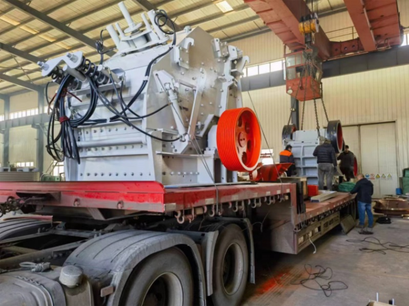
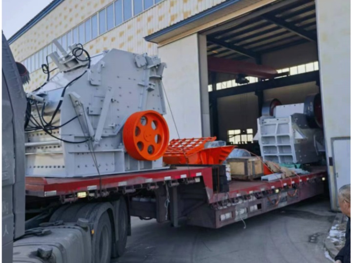
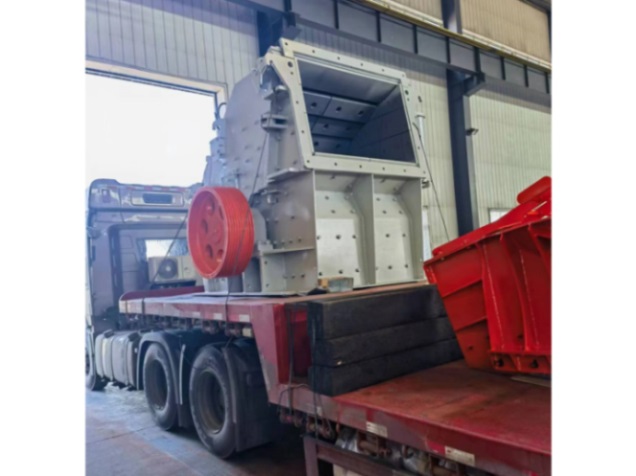
Shipping photos 🔗


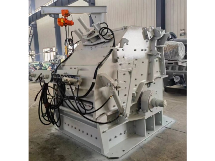
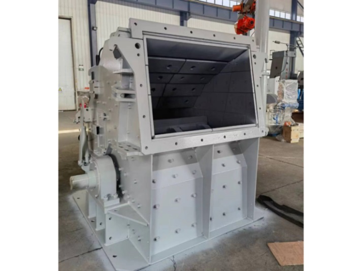
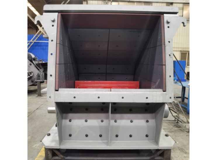
Exhibition photos 🔗


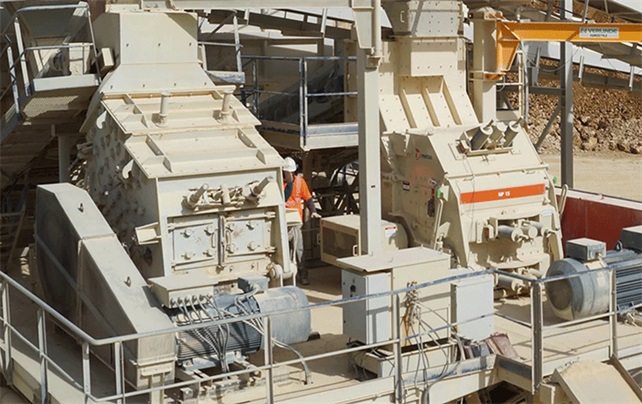
On site photos